 | –≠–ª–µ–∫—Ç—Ä–æ–Ω–Ω—ã–π –∫–æ–º–ø–æ–Ω–µ–Ω—Ç: STV9211 | –°–∫–∞—á–∞—Ç—å:  PDF PDF  ZIP ZIP |
September 2003
Version 4.1
1/37
STV9211
150 MHz PIXEL VIDEO CONTROLLER
FOR MONITORS IN DC-COUPLING MODE
Æ
FEATURES
q
150 M
Hz Pixel Rate
q
2.7 ns Rise and Fall Time
q
I
2
C Bus Controlled
q
Support DC Coupling Application only
q
Brightness Selection (after or before Drive)
q
Grey Scale Tracking Versus Brightness
q
InfraBlack Range Selection 1.3 or 1.8V
(i.e: 26 or 36V in kit with STV95xx amplifier)
q
InfraBlack Offset Selection 0.4 to 2.2V
(i.e: 115 to 80V in kit with STV95xx amplifiers)
q
OSD Mixing
q
Beam Current Attenuation (ABL)
q
Pedestral Clamping on Output Stage
q
Possibility of Light or Dark Grey OSD
Background
q
OSD Contrast Control
q
Input Black Level Clamping with Built-in
Clamping Pulse
q
5 V to 8 V Power Supply
q
Perfectly matched with the STV95xx ST
Amplifier Family
q
Preamplifier Control (bandwidth and stand-by)
q
Amplifier Control (bandwidth and stand-by),
only applicable to amplifiers with CTL pin or
STDBY pins.
DESCRIPTION
The STV9211 is an I
2
C Bus controlled RGB pre-
amplifier designed for Monitor applications, able to
mix the RGB signals coming from any OSD device.
The usual Contrast, Brightness, Drive and Cut-Off
(InfraBlack) Controls are provided.
In addition, it includes the following features:
- High resolution cut-off (InfraBlack) adjustment,
- OSD contrast,
- Bandwidth and stand-by control,
- Brightness before/after Drive Selection.
The RGB incoming signals are amplified and
shaped to drive in DC coupling the video amplifier
without intermediate follower stages.
One of the main advantages of ST devices is their
ability to sink and source currents.
These driving capabilities combined with an original
output stage structure suppress any static current
on the output pins and therefore reduce
dramatically the power dissipation of the device.
Extensive integration combined with high
performance and advanced features make the
STV9211 one of the best choice for any CRT
monitor.
Perfectly matched with the ST video amplifiers
STV95xx, they offer a complete solution for high
performance and cost-optimized Video Board
Application.
DIP20
(Plastic Package)
ORDER CODE: STV9211

STV9211
2/37
STMicroelectronics Confidential
ADCS 7244743
Table of contents
Chapter 1
Pin connection, pin description . . . . . . . . . . . . . . . . . . . . . . . . . . . . . . . . . . . . . .5
1.1
Pin connection ...................................................................................................................... 5
1.2
Pin description ...................................................................................................................... 5
Chapter 2
Functional description . . . . . . . . . . . . . . . . . . . . . . . . . . . . . . . . . . . . . . . . . . . . . .7
2.1
RGB input, clamping function ............................................................................................... 7
2.2
Fast blanking input ............................................................................................................... 8
2.3
Blanking input ....................................................................................................................... 8
2.4
Contrast adjustment (8 bits) ................................................................................................. 9
2.5
Brightness/Drive selection (1 bit) ......................................................................................... 9
2.6
Drive adjustment (3 x 8 bits) .............................................................................................. 10
2.7
Brightness adjustment (8 bits) ............................................................................................ 11
2.8
Cut-off adjustment, Infra-black level (Vib) (3x8 bits) .......................................................... 12
2.9
ABL Control ........................................................................................................................ 14
2.10
OSD ................................................................................................................................... 14
2.11
Output stage ....................................................................................................................... 16
2.12
Preamplifier bandwidth adjustment (4 bits) ........................................................................ 17
2.13
Amplifier bandwidth adjustment (7 bits) ............................................................................. 17
2.14
CRT cathode, DC-coupling mode (
Figure 12
) .................................................................... 18
2.15
Preamplifier stand-by mode ............................................................................................... 18
2.16
Amplifier stand-by mode .................................................................................................... 18
2.17
Serial interface ................................................................................................................... 19
2.18
Power-on reset ................................................................................................................... 19
2.19
Specific application conditions ........................................................................................... 20
Chapter 3
Absolute maximum ratings . . . . . . . . . . . . . . . . . . . . . . . . . . . . . . . . . . . . . . . . .21
Chapter 4
Thermal data . . . . . . . . . . . . . . . . . . . . . . . . . . . . . . . . . . . . . . . . . . . . . . . . . . . . .21
Chapter 5
DC electrical characteristics . . . . . . . . . . . . . . . . . . . . . . . . . . . . . . . . . . . . . . . .22
Chapter 6
AC electrical characteristics . . . . . . . . . . . . . . . . . . . . . . . . . . . . . . . . . . . . . . . .23
Chapter 7
I2C electrical characteristics . . . . . . . . . . . . . . . . . . . . . . . . . . . . . . . . . . . . . . . .25

ADCS 7244743
STMicroelectronics Confidential
3/37
STV9211
Chapter 8
I2C interface timing requirements . . . . . . . . . . . . . . . . . . . . . . . . . . . . . . . . . . .25
Chapter 9
I2C register description . . . . . . . . . . . . . . . . . . . . . . . . . . . . . . . . . . . . . . . . . . . .26
Chapter 10
STV9211 + STV9556/55/53 applications hints . . . . . . . . . . . . . . . . . . . . . . . . . .29
10.1
InfraBlack adjustment procedure (Cut-off) ......................................................................... 29
10.2
Preamplifier bandwidth register .......................................................................................... 31
10.3
Preamplifier output network ............................................................................................... 31
10.4
White balance adjustment .................................................................................................. 31
Chapter 11
Internal schematics . . . . . . . . . . . . . . . . . . . . . . . . . . . . . . . . . . . . . . . . . . . . . . .32
Chapter 12
Demonstration boards . . . . . . . . . . . . . . . . . . . . . . . . . . . . . . . . . . . . . . . . . . . . .34
Chapter 13
Package mechanical data . . . . . . . . . . . . . . . . . . . . . . . . . . . . . . . . . . . . . . . . . .36

STV9211
4/37
Revision follow-up
Target specification
December 2000
version 1.0
document created
January 2001
version 1.1
reformatted with ST new corporate template
January 2001
version 1.2
General update
- replacement of some figures ,
- correction and addition of registers
First ADCS release
April 2001
version 1.3
General update
- replacement of some figures ,
- correction of text,
- addition of sections
June 2001
version 1.4
General update and addition of:
- chapter 10: Application hints,
- chapter 11: Internal, schematics,
- chapter 12: application boards
Product preview
October 2001
version 2.0
General update:
- replacement of some figures,
- addition of sections : cut-off adjustment...,
- addition of figures (I2C, Cut-off adjustment)
- TDA95xx salestype replaced with STV95xx
Preliminary data
December 2001
version 3.0
General update
- figures replaced
- Cut-off replaced with Infra-Black
Datasheet
January 2002
version 4.0
section 1.2: pin description modified for IN1, IN2, IN3, OSD1, OSD2,
OSD3 and OUT1, OUT2, OUT3: replaced with video input, OSD
input, Video output (channel 1, red), (channel 2, green), (channel 3,
blue) respectively
Block diagram replaced
section 2.3 Blanking input added
Section 2.8 - Cut-off adjustment: Tables 1 and 2 gathered into table 1
Section 2.12 - preamplifier bandwidth adjustment (4 bits) instead of 3
bits previously
Chapter 10 - Application hints
tables 9 and 10 replaced with table 1
Cross reference to AN1445 replaced with AN1510
February 2003
version 4.1
Text changed in section 2.2.
Text changed and figure removed in section 2.3.
5/37
STV9211
Pin connection, pin description
1
PIN CONNECTION, PIN DESCRIPTION
1.1
Pin connection
1.2
Pin description
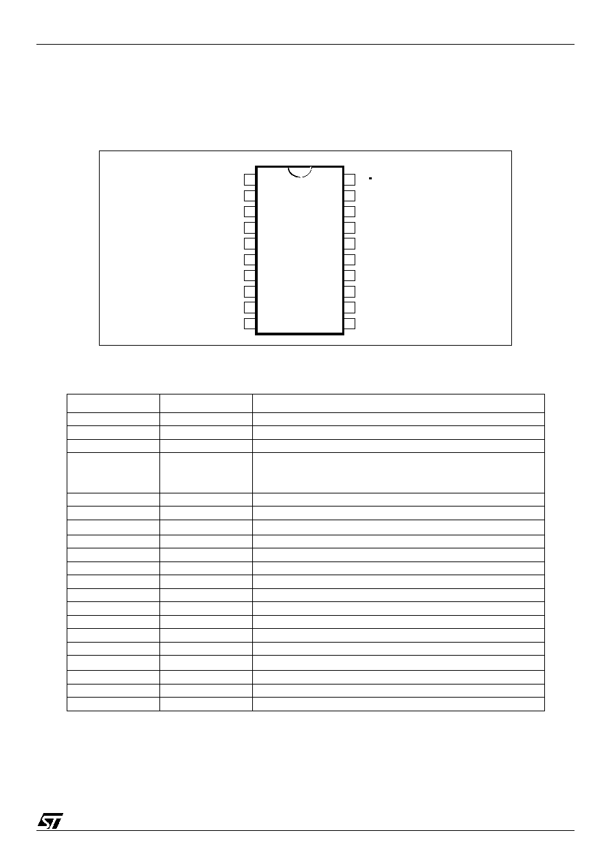
Figure 1: STV9211 pin connection
Pin number
symbol
description
1
IN1
Video input (channel 1, red)
2
ABL
ABL input
3
IN2
Video input (channel 2, green)
4
AMPCTL
Amplifier control (bandwidth and stand-by). Only applicable with
amplifiers with the CTL or STDBY pins.
To be connected to ground if not used.
5
IN3
Video input (channel 3, blue)
6
GNDA
Analog ground
7
V
CCA
Analog supply (5V)
8
OSD1
OSD input (channel 1, red)
9
OSD2
OSD input (channel 2, green)
10
OSD3
OSD input (channel 3, blue)
11
FBLK
Fast blanking
12
SCL
SCL
13
SDA
SDA
14
OUT3
Video output (channel 3, blue)
15
GNDP
Power ground
16
OUT2
Video output (channel 2, green)
17
V
CCP
Output stage supply (5 V to 8 V)
18
OUT1
Video output (channel 1, red)
19
HS
Horizontal synchro or BPCP pulse
20
BLK
Blanking input
BLK
IN1
ABL
IN2
AMPCTL
IN3
GNDA
V
CCA
OSD1
OSD2
OSD3
FBLK
HS
OUT1
V
CCP
OUT2
GNDP
OUT3
SDA
SCL
1
2
3
4
5
6
7
8
9
10
11
12
20
19
18
17
16
15
14
13